request to quote
Leave Your Message

What Is Complex Structure Welding?

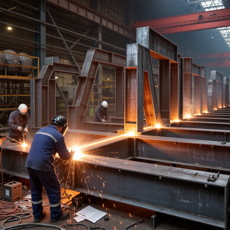
Complex Structure Welding involves joining irregular, load-bearing components into one controlled assembly. It appears in bridges, pressure vessels, heavy machinery, offshore frames, and industrial equipment. Unlike simple butt welding, these projects combine varying thicknesses, joint angles, materials, and access limitations. Every weld affects the structure’s load path.

The work begins with detailed drawings, material identification, joint preparation, and a qualified welding procedure. Fit-up matters. A small root gap can change penetration, distortion, and final alignment. Experienced welders monitor heat input, interpass temperature, and sequence during fabrication. They also consider residual stress, shrinkage, and difficult visual access. Inspection may include visual testing, ultrasonic testing, radiography, or magnetic particle testing, depending on the design and applicable standards.

Still, no welding plan is perfect. Site conditions change. Components may arrive slightly distorted. That reality demands informed adjustments, not careless improvisation. Engineers and inspectors must document changes and confirm that repairs remain technically acceptable. A confident appearance does not prove structural reliability. Evidence does.

This guide explains the principles behind Complex Structure Welding, from planning and material control to welding sequences and inspection. It also examines common failures, including cracking, lack of fusion, excessive distortion, and incomplete penetration. Some problems begin before the arc starts. That is easy to overlook.

Reliable results require cooperation among designers, fabricators, welders, and inspectors. Their decisions should reflect approved procedures, traceable records, and recognized engineering standards. Proper training remains essential, but experience alone cannot replace verification. Each complex assembly deserves careful judgment, measurable quality, and honest review.
What Is Complex Structure Welding?

Definition and Scope of Complex Structure Welding

What Is Complex Structure Welding?

Definition and Scope of Complex Structure Welding

Complex structure welding joins steel or other metals into assemblies with difficult geometry, changing thickness, or demanding load paths. It may involve bridges, pressure vessels, offshore frames, heavy equipment, and custom industrial modules. The work includes joint design, material preparation, welding procedure qualification, distortion control, inspection, and traceable documentation.

The scale is substantial. World Steel Association reported 1.89 billion tonnes of crude steel production worldwide in 2023, showing the material base behind modern structural fabrication. However, complex welding is not simply high-volume welding. A single joint may require several passes, controlled heat input, preheating, and careful sequencing around stiffeners. A small angular error can create visible distortion.

Its scope also includes people and systems. The U.S. Bureau of Labor Statistics projects about 42,600 annual openings for welders, cutters, solderers, and brazers from 2023 to 2033. That demand reflects both fabrication and repair work. Competent practice depends on qualified welders, approved procedures, calibrated equipment, and inspection methods such as visual, ultrasonic, or radiographic testing. ISO 3834 places quality requirements across these production controls.

The boundary is not always clean. A simple-looking frame may become complex after access limits, residual stress, or fatigue requirements appear. In practice, drawings rarely reveal every risk. Field experience still matters. Mistakes in sequencing can expose weaknesses that calculations miss.
Materials, Joint Designs, and Structural Components

What Is Complex Structure Welding?

Materials, Joint Designs, and Structural Components

Complex structure welding connects materials that behave differently under heat, stress, and vibration. Carbon steel remains common, while stainless steel, aluminum, and high-strength alloys demand tighter control. The World Steel Association reported approximately 1.89 billion tonnes of crude steel production in 2023. That scale shows why weld quality affects major infrastructure. Material thickness, thermal expansion, and surface contamination can change the final joint.

Joint design matters as much as welding technique. Butt joints provide direct load paths, while fillet joints suit frames, brackets, and stiffeners. Lap joints can simplify fabrication, but they may trap moisture and encourage corrosion. Structural components often include beams, columns, trusses, pressure-supporting frames, and connection plates. Each part needs a suitable weld size, access route, and inspection plan. The American Welding Society’s structural guidance emphasizes qualified procedures, welder competence, and documented inspection. Still, real projects are rarely perfect. Tight corners, distorted plates, and limited access can defeat a clean drawing.

Tips: Match the filler material to the base metals. Control preheat and interpass temperature. Check fit-up before striking an arc. Record weld parameters and inspection results. Radiographic or ultrasonic testing can reveal hidden flaws, but neither replaces careful workmanship. The U.S. Bureau of Labor Statistics projects about 42,600 annual openings for welding-related workers from 2022 to 2032. Skilled judgment remains essential. Automation helps, but it does not understand every awkward joint.

Welding Processes Used for Complex Structures

Complex structure welding joins beams, plates, tubes, and stiffeners into load-bearing assemblies. It demands controlled heat, accurate fit-up, and a welding process suited to each joint. A bridge node, pressure vessel, or offshore frame may require several processes in one assembly. The 2023 workforce report from the American Welding Society estimated that the United States could need 330,000 new welding professionals by 2026. That shortage makes process discipline even more important.

GMAW suits repeated structural joints because it offers consistent wire feeding and productive deposition rates. FCAW performs well on thicker steel, especially where wind makes shielding gas unreliable. GTAW gives precise control for root passes, thin sections, and critical alloy connections. SAW can deposit large weld volumes on long, accessible seams. Robotic welding also supports repeatability; the International Federation of Robotics reported 541,302 industrial robot installations worldwide in 2023. Automation helps, but it cannot correct poor joint design.

Heat control matters. Welders sequence short passes around a frame to reduce distortion. They may use temporary strongbacks, calibrated preheating, and interpass temperature checks. A clean bead can still conceal incomplete fusion or hydrogen cracking. Visual inspection alone is not enough for critical structures. Ultrasonic or radiographic testing may reveal defects below the surface. The difficult part is choosing the simplest reliable process, not the most advanced one. That judgment still deserves review.

Planning, Fit-Up, and Execution Procedures

What Is Complex Structure Welding?

Planning, Fit-Up, and Execution Procedures

Complex structure welding joins members with changing angles, uneven access, and demanding load paths. It requires more than selecting a welding process. Planning begins with the approved drawings, material certificates, weld maps, and a clear sequence. Each joint should identify its weld size, position, inspection method, and acceptance criteria. The 2023 American Welding Society workforce report projects a need for 330,000 new welding professionals in the United States by 2028. That shortage makes repeatable procedures increasingly important.

Fit-up controls the final geometry. Fabricators check root openings, bevel angles, alignment, temporary attachments, and restraint before tack welding. Small errors can become large distortions after several passes. A practical approach uses calibrated gauges, reference datums, and staged dimensional checks. Keep records. Fit-up is often rushed, and that remains a serious weakness.

Execution follows the qualified welding procedure specification. Operators verify preheat, interpass temperature, consumable condition, travel speed, and heat input. For thick or restrained sections, a balanced welding sequence can reduce angular distortion. Inspectors may use visual testing, ultrasonic testing, magnetic particle testing, or radiography, depending on the design requirements. ISO 3834 emphasizes controlled welding quality systems, including personnel competence, equipment control, and traceability. Still, paperwork cannot correct poor access or an unrealistic weld sequence. A dry mock-up or trial fit can expose those problems before production begins.

What Is Complex Structure Welding? - Planning, Fit-Up, and Execution Procedures

Work Stage Main Objective Key Inputs and Dimensions Recommended Controls Typical Acceptance Considerations Required Records
1. Engineering Review Convert design information into an executable welding plan. Material grade and thickness; joint type; weld size; access limitations; design loads; distortion-sensitive dimensions. Confirm approved drawings, welding procedures, inspection requirements, weld symbols, and sequence before fabrication. All joints have an identified procedure, inspection method, welder qualification requirement, and acceptance standard. Drawing review checklist; weld map; procedure register; inspection and test plan.
2. Material Verification Prevent incorrect or contaminated material from entering the assembly. Plate, pipe, section, or casting identification; thickness; heat number; material certificate; surface condition. Check identification against drawings and certificates. Separate carbon steel, stainless steel, and other alloys to avoid cross-contamination. Material grade, thickness, and traceability agree with the approved design documents; surfaces are free from oil, moisture, scale, and loose rust. Material receiving report; certificates; traceability log; nonconformance report when applicable.
3. Joint Preparation Produce a joint geometry that supports complete fusion and controlled penetration. Bevel angle; root face; root opening; alignment; edge straightness; backing or run-on/run-off arrangement. Measure the joint with calibrated tools. Remove laminations, burrs, sharp notches, and excessive gouging damage before fit-up. Joint dimensions remain within the tolerances specified by the approved welding procedure or project specification; no unauthorized gap filling is used. Fit-up inspection report; dimensional readings; corrective-action record.
4. Fit-Up and Tack Welding Hold components in the correct position while preserving the required joint geometry. Overall length, width, elevation, squareness, centerline, root gap, offset, temporary attachments, and tack locations. Use approved fixtures and strongbacks where necessary. Distribute tacks symmetrically and remove cracked or defective tacks before final welding. Assembly is stable; dimensional tolerances meet the drawing; tack welds are sound, compatible with the final procedure, and free from visible cracks. Fit-up release; tack-weld inspection; temporary attachment log; dimensional inspection sheet.
5. Preheat and Interpass Control Control cooling rate, hydrogen risk, and weld-metal properties. Minimum preheat; maximum interpass temperature; material thickness; carbon equivalent; ambient temperature; moisture conditions. Measure temperature on both sides of the joint when required, at a specified distance from the weld, using calibrated temperature instruments. Temperatures remain within the approved procedure range throughout welding; the joint is dry and protected from rain, condensation, and excessive drafts. Preheat log; interpass temperature record; weather or environmental monitoring log.
6. Welding Execution Deposit sound weld metal while managing heat input and structural distortion. Welding process; electrode or wire classification; polarity; amperage; voltage; travel speed; weld position; pass sequence. Follow the approved procedure. Use balanced sequencing, skip or block welding where specified, clean every pass, and control arc strikes. No visible cracks, lack of fusion, unacceptable undercut, excessive overlap, arc strikes, or other discontinuities permitted by the governing acceptance criteria. Welder identification; welding parameters; consumable usage; pass sequence; weld completion report.
7. Distortion Management Maintain geometry and reduce corrective work after welding. Angular distortion; shrinkage; bowing; twisting; flange spacing; straightness; connection alignment. Use pre-set dimensions, balanced weld sequences, temporary restraints, intermittent welds where designed, and controlled heating only when authorized. Final dimensions remain within drawing tolerances; correction does not introduce cracks, buckling, harmful residual stress, or surface damage. Dimensional survey; distortion report; heat-correction record; repair approval.
8. Weld Cleaning and Visual Inspection Identify surface defects before non-destructive testing or coating. Weld profile; crater condition; surface discontinuities; spatter; slag; undercut; overlap; arc strikes. Clean welds and adjacent surfaces. Inspect with suitable lighting and calibrated gauges before releasing the work to the next stage. Weld profile and surface condition comply with the applicable specification; unacceptable indications are repaired and re-inspected. Visual inspection report; weld gauge readings; repair and re-inspection record.
9. Non-Destructive Examination Detect internal or surface-breaking discontinuities that visual inspection cannot confirm. Examination method; weld category; inspection extent; access; surface preparation; timing after welding where specified. Select visual, liquid penetrant, magnetic particle, ultrasonic, or radiographic examination according to the approved inspection plan. Results meet the acceptance criteria stated in the contract, code, drawing, or approved procedure; rejected welds follow a documented repair sequence. NDE reports; examiner qualification evidence; image or scan records where applicable; repair map.
10. Final Dimensional Verification Confirm the completed structure can be assembled, installed, and loaded as designed. Overall dimensions; hole or nozzle locations; elevations; flatness; squareness; plumbness; connection fit; access clearance. Use calibrated measuring equipment and a controlled datum system. Compare as-built results with approved drawings. All critical dimensions and interfaces fall within approved tolerances; deviations are reviewed and formally accepted before release. As-built dimensional report; survey data; deviation approval; release certificate.
11. Surface Protection and Handover Protect the completed weldment and provide complete quality evidence. Surface cleanliness; coating or preservation system; dry-film thickness where applicable; weld identification; outstanding items. Remove weld spatter and temporary attachments, repair surface damage, apply the specified protection, and close all inspection points. Coating and preservation meet the approved specification; traceability, inspection, repair, and dimensional records are complete. Coating inspection report; punch-list closure; weld dossier; final handover package.
Important: Numerical tolerances, preheat temperatures, interpass limits, weld sizes, inspection percentages, and acceptance criteria must be taken from the approved drawings, welding procedure, contract specification, and governing construction code for the specific structure.

Inspection, Safety, and Quality Control Requirements

Complex structure welding demands tighter control than ordinary joint fabrication. Members may meet at changing angles, with limited access and uneven heat flow. These conditions increase distortion, residual stress, and hidden lack of fusion. Small deviations matter.

A reliable inspection plan begins before arc initiation. Review approved drawings, weld procedures, material certificates, and welder qualifications. Confirm joint preparation, root gap, alignment, preheat, and consumable control. During welding, record interpass temperatures and inspect each pass when access permits. Visual inspection should check profile, undercut, overlap, arc strikes, and surface cracks. Ultrasonic or radiographic examination may be specified for critical connections. Dimensional checks are equally important; a sound weld can still place a frame outside tolerance.

Safety controls must match the structure. Use engineered platforms, fall protection, ventilation, fire watches, and verified electrical grounding. Confined or poorly ventilated spaces require atmospheric testing and a rescue plan. Keep inspection records traceable to welders, materials, locations, and repair cycles. I have learned that rushed fit-up often creates more rework than welding itself. Conditions change. Inspectors should question unclear acceptance criteria and stop work when conditions change. That hesitation can protect the joint, the crew, and the schedule.