request to quote
Leave Your Message

What Is Building Steel Structure Welding?

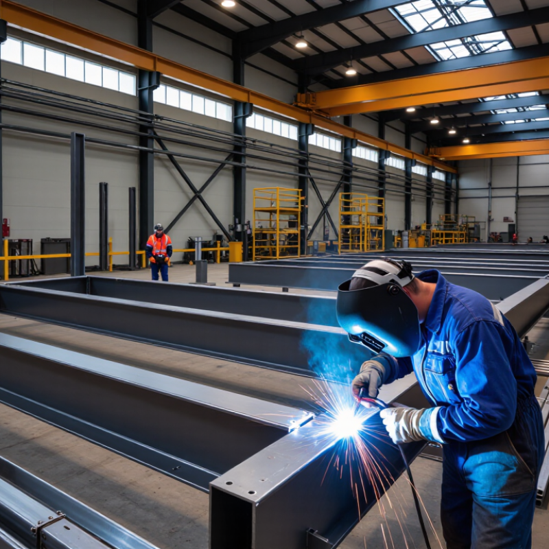
Building Steel Structure Welding is where structural design becomes a load-bearing reality. It joins beams, columns, bracing members, and connection plates under strict technical controls. The work demands more than a visible weld bead. Fit-up, joint preparation, heat input, shielding gas, and inspection all influence structural performance.

The World Steel Association reported 1.888 billion tonnes of crude steel production worldwide in 2023. That volume reflects steel’s continuing importance in construction and infrastructure. However, production figures do not measure welding quality. The U.S. Bureau of Labor Statistics projects about 45,400 annual openings for welders, cutters, solderers, and brazers from 2024 to 2034. This signals steady demand, but it also highlights a skills gap. Training alone is not enough.

Charlie Carter, former president of the American Institute of Steel Construction, stated, “Steel is the most recycled material in the world.” His observation supports steel’s sustainability, yet recycling does not excuse poor fabrication. A misaligned flange can create stress before a building carries its first load. A small lack of fusion may remain hidden until inspection or service. That is uncomfortable, but important.

This guide examines Building Steel Structure Welding through codes, procedures, inspection methods, and jobsite experience. It considers AWS D1.1 requirements, qualified welders, nondestructive testing, and traceable documentation. Standards provide control. Skilled judgment still matters. No report replaces careful observation beside the weld.

What Is Building Steel Structure Welding?

Definition and Purpose of Building Steel Structure Welding

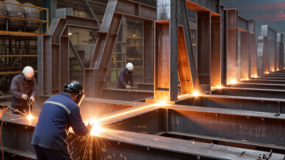
Building steel structure welding is the controlled process of joining steel members through heat, pressure, or both. It connects beams, columns, plates, and braces into a load-bearing frame. The weld must transfer forces safely across each joint. Its purpose is not only to hold steel together. It also supports structural strength, stability, dimensional accuracy, and long-term service performance.

Qualified welders follow approved procedures for joint design, electrode selection, heat control, and inspection. They remove rust, oil, moisture, and mill scale before welding. Poor preparation can create porosity, cracks, or incomplete fusion. A clean-looking weld is not always a sound weld. Inspectors may check weld size, surface defects, alignment, and internal quality through suitable testing methods. Site conditions matter too. Wind, rain, and low temperatures can change the result. Small deviations may become serious when many connections carry repeated loads.

Tips: Confirm drawings and weld details before work begins. Keep steel surfaces dry and clean. Control preheating and interpass temperature when required. Use calibrated equipment and traceable inspection records. Watch distortion during long welds, especially on thin plates. Experienced teams still review their methods because a familiar joint can hide an unusual problem. Visual inspection is valuable, but it cannot reveal every internal defect. Clear communication between fabricators, engineers, and inspectors helps protect the structure and the people who use it.

Key Materials, Welding Methods, and Equipment

Building steel structure welding starts with material control, not the arc. Structural steel must match the design grade, thickness, and traceable test records. Plates, beams, and hollow sections need clean edges. Remove mill scale, moisture, oil, and loose rust near the joint. Welding consumables should suit the base metal and approved procedure. Electrodes and flux require dry storage. Damp consumables can cause porosity or cracking. Fit-up matters too. A two-millimeter gap can change penetration and distortion.

SMAW is practical for repairs and remote work, while GMAW provides steady wire feeding in controlled shop conditions. FCAW handles thicker sections and outdoor fabrication effectively, with suitable shielding. SAW can weld long, straight seams efficiently, but it requires accurate alignment and access. Each method depends on current, voltage, travel speed, polarity, and heat input. Preheating may reduce hydrogen-related cracking in thicker or restrained joints. Interpass temperature also deserves attention. I have seen clean-looking beads fail when fit-up was rushed.

A reliable setup includes a calibrated power source, wire feeder or electrode holder, leads, a secure ground clamp, and gas equipment when required. Welders also use temperature crayons, gap gauges, grinders, screens, helmets, gloves, and flame-resistant clothing. Ventilation is essential because fumes accumulate quickly around enclosed frames. Visual inspection checks bead shape, undercut, overlap, spatter, and arc strikes. Ultrasonic or radiographic testing may be specified for critical joints. Records should capture welder qualification, consumable batch, preheat readings, and repair locations. The process is controlled, but never perfect. Small documentation gaps deserve a second look.

What Is Building Steel Structure Welding? - Key Materials, Welding Methods, and Equipment
Category Item or Parameter Typical Specification or Range Role in Steel Structure Welding Important Technical Considerations
Base Material Structural carbon steel Common yield strength: approximately 235–355 MPa Used for columns, beams, braces, plates, and welded connection components. Preheat and heat input should be selected according to thickness, carbon equivalent, restraint, and project requirements.
Base Material High-strength low-alloy steel Typical yield strength: approximately 355–690 MPa Provides higher strength-to-weight performance in heavily loaded structural members. Requires controlled heat input and suitable low-hydrogen consumables to help preserve mechanical properties and reduce cracking risk.
Base Material Steel plate and sections Typical structural thickness: approximately 6–50 mm, depending on the member Forms the main load-bearing parts of frames, trusses, platforms, and industrial structures. Surface condition, lamellar tearing susceptibility, joint access, and distortion control should be evaluated before welding.
Filler Material Shielded metal arc welding electrodes Common electrode diameters: approximately 2.5–5.0 mm Deposit weld metal for field joints, repair work, erection connections, and locations with limited access. Low-hydrogen electrodes generally require dry storage and controlled exposure to minimize hydrogen-assisted cracking.
Filler Material Solid wire for gas metal arc welding Common wire diameters: approximately 0.8–1.6 mm Supports efficient shop and site welding of carbon and low-alloy structural steel. Wire selection must match the base metal, shielding gas, welding position, and required strength classification.
Filler Material Flux-cored wire Common wire diameters: approximately 1.0–2.4 mm Provides high deposition rates for thick plates, fillet welds, and outdoor or large-scale fabrication work. Gas-shielded and self-shielded types have different operating requirements; slag removal is needed between passes.
Welding Method Shielded Metal Arc Welding (SMAW) Typical current: approximately 70–250 A; usable in most positions Flexible process for field erection, structural repairs, short welds, and difficult-to-reach joints. It has relatively low deposition efficiency and requires electrode changes and slag removal between passes.
Welding Method Gas Metal Arc Welding (GMAW) Typical current: approximately 100–350 A; solid wire with external shielding gas Efficiently produces continuous welds in controlled workshop and fabrication environments. Wind can disrupt shielding gas outdoors. Correct voltage, wire feed speed, gas flow, and contact-tip distance are essential.
Welding Method Flux-Cored Arc Welding (FCAW) Typical current: approximately 150–400 A; self-shielded or gas-shielded wire Used for high-productivity fillet and groove welds on structural frames and thick steel members. Offers good deposition rates, but slag, fumes, and spatter must be managed through correct parameters and ventilation.
Welding Method Submerged Arc Welding (SAW) Typical current: approximately 300–1,000 A; commonly used for long, accessible welds Produces deep penetration and high deposition rates on beams, built-up sections, box columns, and long seams. Generally limited to flat or horizontal welding positions and requires flux handling and suitable joint alignment.
Welding Method Gas Tungsten Arc Welding (GTAW) Typical current: approximately 50–250 A; non-consumable tungsten electrode Used when high control and clean welds are required, especially for thin sections or specialized steel components. It provides excellent weld quality but has a lower deposition rate than most structural production processes.
Joint Type Fillet weld Common leg size: approximately 4–12 mm, subject to design calculations Joins overlapping plates, angles, stiffeners, brackets, and beam-to-column connection components. Actual size must satisfy design strength, minimum weld size, maximum size, access, and corrosion-control requirements.
Joint Type Groove weld Partial or complete joint penetration Joins plates or sections aligned edge-to-edge when higher load capacity or full continuity is required. Joint preparation, root opening, groove angle, backing, and inspection requirements strongly affect weld performance.
Joint Type Plug or slot weld Weld deposited through a hole or elongated slot Transfers shear or connects overlapping steel components where conventional edge access is limited. Hole or slot dimensions, spacing, plate thickness, and accessibility should follow the applicable structural design standard.
Power Source Constant-current welding power source Commonly used for manual electrode welding and some tungsten arc applications Helps maintain a stable arc when the operator varies arc length. Correct polarity and output range must be selected for the electrode type, diameter, and welding position.
Power Source Constant-voltage welding power source Commonly used for wire-feed processes Works with wire feed speed to control arc behavior and deposition rate. Voltage, wire feed speed, inductance, travel speed, and shielding gas must be balanced to prevent defects.
Workshop Equipment Positioner or turning fixture Capacity selected according to component weight and dimensions Rotates or repositions workpieces to improve welding position, access, and productivity. Proper clamping and load control help prevent movement, unsafe handling, and dimensional inaccuracies.
Workshop Equipment Fit-up and clamping tools Strongbacks, clamps, wedges, jigs, and temporary attachments Maintain alignment, root opening, squareness, and dimensional stability before and during welding. Temporary attachments should be designed and removed carefully so they do not introduce cracks or harmful gouges.
Workshop Equipment Preheating equipment Electric resistance heaters, induction heaters, or controlled gas heating Raises and maintains the required steel temperature before and during welding. Temperature should be measured with suitable contact or infrared instruments, considering emissivity when applicable.
Workshop Equipment Cleaning and preparation tools Grinders, wire brushes, chipping hammers, and cutting equipment Remove rust, mill scale, paint, moisture, slag, and other contaminants from the weld area. Excessive grinding can reduce section thickness or create sharp notches; cleaned surfaces should remain dry before welding.
Safety Equipment Welding helmet and eye protection Shade selected according to welding process and current Protects the eyes and face from ultraviolet radiation, infrared radiation, sparks, and molten metal. Additional safety glasses or face protection may be required for grinding, chipping, and cutting operations.
Safety Equipment Fume extraction and ventilation Local exhaust ventilation preferred at the weld source Controls welding fumes, gases, and airborne contaminants in workshops and enclosed work areas. Ventilation must not disturb shielding gas or replace the need for suitable respiratory protection where required.
Quality Control Visual testing (VT) Applicable to accessible weld surfaces and completed joints Detects visible cracks, undercut, overlap, porosity openings, arc strikes, poor profile, and dimensional issues. Inspection should be performed before painting or coating and at defined stages during fabrication.
Quality Control Magnetic particle testing (MT) For ferromagnetic steel surfaces and near-surface discontinuities Helps locate surface and slightly subsurface cracks in structural steel welds and heat-affected zones. The test area must be properly prepared, and interpretation should be performed by qualified personnel.
Quality Control Ultrasonic testing (UT) Commonly used for thicker sections and complete-joint-penetration welds Detects internal discontinuities such as lack of fusion, incomplete penetration, and planar indications. Results depend on joint geometry, calibration, access, surface condition, and operator qualification.
Quality Control Radiographic testing (RT) Uses X-rays or gamma radiation to examine internal weld quality Reveals volumetric discontinuities such as slag inclusions and porosity in suitable weld configurations. Requires controlled exclusion zones, radiation safety procedures, and appropriate image interpretation.
Process Control Heat input Calculated from voltage, current, travel speed, and process efficiency Influences penetration, cooling rate, distortion, toughness, and heat-affected-zone properties. Excessive or insufficient heat input can reduce weld performance; approved welding procedures should define acceptable limits.
Process Control Preheat and interpass temperature Project-specific; often controlled from ambient temperature to several hundred degrees Celsius Controls cooling rate and reduces the risk of hydrogen-assisted cracking in restrained or thick joints. Requirements depend on steel grade, thickness, carbon equivalent, consumable hydrogen level, and environmental conditions.
Common Defect Porosity Gas cavities trapped in weld metal May reduce effective weld area and indicate contamination or inadequate shielding. Common causes include moisture, oil, rust, excessive gas flow, drafts, or an incorrect torch and contact-tip position.
Common Defect Lack of fusion or incomplete penetration Unfused surfaces or insufficient weld penetration at the joint root Can significantly reduce connection strength and fatigue performance. Usually controlled through proper joint preparation, sufficient energy, correct travel speed, and appropriate electrode angle.
Common Defect Weld distortion Angular, longitudinal, or transverse deformation May affect member alignment, fit-up, load transfer, and installation accuracy. Balanced welding sequences, suitable tack welds, restraints, presetting, and controlled heat input help reduce distortion.

How Steel Structural Welding Is Performed Step by Step

Building steel structure welding connects prepared steel members into load-bearing frames. The work demands more than melting metal. It requires controlled heat, accurate fit-up, qualified procedures, and documented inspection. The World Steel Association reported approximately 1.9 billion tonnes of crude steel production in 2023, showing the scale of steel construction worldwide.

The process begins with approved drawings and a qualified Welding Procedure Specification. Welders verify steel grades, joint details, electrode condition, and traceability records. Surfaces are cleaned of mill scale, oil, moisture, and rust. Fit-up comes first. Workers align columns, beams, and plates, then use measured tack welds to hold the geometry. Small gaps can create major distortion.

Heat matters. Preheating is applied when the procedure requires it, especially for thicker or higher-strength steel. The welder then deposits controlled passes, managing travel speed, amperage, and interpass temperature. Each layer may need cleaning before the next pass. Welding sequence also limits shrinkage and frame movement. It is not always perfect. Site access, wind, and cramped joints can challenge even experienced crews.

After welding, inspectors examine weld size, profile, undercut, porosity, and visible cracking. Critical connections may receive ultrasonic or magnetic-particle testing under the project specification. AWS D1.1 and AISC 360 provide widely recognized requirements for structural steel welding and design. Repairs must follow an approved method, not personal guesswork. Some teams still underestimate fit-up time. That is a costly lesson.

Quality Standards, Inspection, and Common Welding Defects

What Is Building Steel Structure Welding?

Quality Standards, Inspection, and Common Welding Defects

Building steel structure welding joins columns, beams, braces, and connection plates into a load-bearing frame. Quality depends on more than a smooth weld bead. The welding procedure should define joint preparation, filler material, current range, preheating, and pass sequence. Welders also need suitable qualifications for the joint type and welding position. Fit-up matters greatly. A wrong root gap can create trouble before the arc starts.

Inspection usually begins with visual checks. Inspectors examine weld size, profile, undercut, overlap, cracks, arc strikes, and surface porosity. They also verify alignment and distortion against approved drawings. For concealed or highly stressed joints, ultrasonic or magnetic particle testing may be required. Inspection tools must be calibrated, and records should identify the welder, joint, procedure, and test result. Traceability supports reliable decisions.

Common defects include porosity, slag inclusions, lack of fusion, incomplete penetration, cracks, and excessive distortion. Moisture, contamination, incorrect travel speed, and poor shielding can cause many of them. A clean surface can still hide internal flaws. That is why visual inspection alone is sometimes insufficient. In practice, rushed repairs often create new defects. Weld maps, repair procedures, and reinspection reduce this risk. One detail deserves reflection: a passing report does not excuse weak workmanship, because site conditions can change after inspection.

Safety Practices and Applications in Building Construction

What Is Building Steel Structure Welding?

Building steel structure welding joins columns, beams, braces, and connection plates into a load-bearing frame. The process may use shielded metal arc, gas metal arc, or flux-cored welding. Each method requires qualified workers, controlled settings, and verified joint designs.

Safety begins before the arc starts. A competent supervisor should inspect cables, grounding, cylinders, screens, and nearby combustible materials. The National Fire Protection Association reported an average of 4,580 U.S. structure fires caused by hot work each year from 2014 to 2018. These fires caused approximately 12 deaths, 166 injuries, and 484 million dollars in property damage. A fire watch remains necessary after welding ends. Sparks can travel through small floor gaps.

Welding fumes require equal attention. The International Agency for Research on Cancer classifies welding fumes as carcinogenic to humans. Local exhaust ventilation, suitable respirators, and exposure monitoring can reduce inhalation risks. Workers also need flame-resistant clothing, gloves, eye protection, and fall protection when welding above ground. Steel surfaces may look stable, yet temporary connections can shift suddenly. This is where experience matters. I have seen teams focus on weld appearance while overlooking access, ventilation, or heat distortion. That is a costly weakness. Inspection should include visual checks, dimensional measurements, and non-destructive testing when the design requires it. Poor fit-up still happens, even on experienced sites. Clear drawings, traceable weld procedures, and honest inspection records help prevent small defects from becoming structural problems.